ColourSpace can be used for manual Display Calibration, using any display's in-built Colour Management System (CMS) to calibrate the display as accurately as possible using the display's provided adjustment options.
Using this guide it should be possible to get accurate results from ColourSpace without having to fully understand the software, although it is highly recommended to learn and fully understand the tools within ColourSpace as there are many, many additional capabilities not covered by this guide.
- ColourSpace INF/XPT/PRO/CAL/LTE & HTX/HTP/HTL & DPS/ZRO
ColourSpace Manual Display Calibration
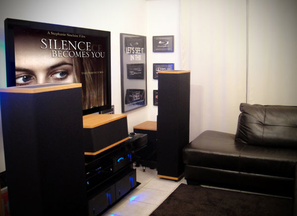
The real requirement for display calibration is actually very obvious, as without it you will never see images as the production team, specifically the DoP & Colourist, intends. This is true for displays used on film and TV productions, as well as for the home consumer, be it Gaming or Home Cinema use. It is equally true for Medical applications, where medical image assessment requires critical display calibration.
Grading Displays Why Calibrate
Therefore, display calibration is required so that the viewed images match as closely as possible the colour standards expected by the images being viewed.
Unfortunately, nearly all displays are provided with very poor factory calibration out of the box, especially home TVs which tend to come with over saturated colours, widely inaccurate gamma/EOTF and colour temperature, and incorrect black and white levels, with such settings aimed at looking pretty in the TV show-room.
Beyond this, many TVs have what are claimed as professional calibration pre-sets, such as ISF or THX. Unfortunately such settings are often nothing more than marketing gimmicks, as rarely are they accurate. At best, they are just less wrong.
(That is not to belittle the intentions of the ISF or THX - it is just simple fact that no factory calibration can ever be accurate, as the same settings are applied en-mass to all TVs of the same model, as dictated by cost.)
Regardless of the initial state of any factory calibration, all displays drift over time, and should be recalibrated on a regular basis. We recommend at least once a month, and manufacturers, such as EIZO, concur with this:
When using a monitor for graphics, stable colour can be maintained at all times by conducting calibration at a frequency of once every 200–300 hours. An LCD monitor used for graphics should be calibrated at least once every 200–300 hours (in ordinary use, once per month).
ColourSpace Manual Calibration Process
There are 6 main steps to Manual Calibration of home TVs, assuming the TV in question has good internal manual CMS controls, and this guide provides a step-by-step overview to the best-practice approach for manual TV calibration.
-
Black & White levels
Set-up basic Black level & White levels, avoiding any clipping/crushing
-
Peak White
Set peak white to the desired value
-
Best Picture Mode
Finding the picture mode to best match the target colour space
-
Gamma
Finding the gamma/EOTF setting to best match the target colour space
-
Grey Scale/White Balance
Configuring the grey scale and white point colour temperature
-
Gamut/Colour
Setting the gamut/colour to best match the target colour space
While the above list is fairly simple, it will be necessary to re-visit most entries for a second, or even third time, after checking other entries. For example, the black & white levels will need to be re-verified after the best Picture Mode has been found - but you really need to set the black and white levels before evaluating the display's different Picture Modes, as incorrect black & white levels will make any Picture Mode look wrong...
It is imperative to understand that such a repetitive and circular approach to manual calibration is a requirement due to the way just about all manual TV calibration controls work.
Manual Display Controls
The actual controls that will be used during manual calibration will vary depending on what is provided by the specific display being calibrated. Knowing what controls are available, and what they are used for is a critical step in gaining accurate final calibration.
It is also important to note that many home TV displays have very poor controls, to the point that some controls do not work as expected (including wrong control labeling, incorrect functionality, and just plain poor design!). It really is key to know if the display in question has controls that operate as expected, or not.
Picture Mode
On Home TVs, Picture Mode selects different display-wide settings, on-top of which the other display controls work (often with different controls active or not, depending on the Picture Mode selected). For accurate display calibration the need is to find the mode that is the least inaccurate. This is usually Movie or Cinema mode, which contrary to their names is actually closer to a the correct colour and gamma/EOTF calibration for TV's, and has nothing to do with trying to emulate Cinema imagery. Additionally, when selecting these modes many home TVs provide additional manual controls, as described below. If a User Mode is available, that is often the best to select, as it provides the best blank canvas with which to work, with the best selection of additional manual controls.
Colour Profile
Colour Profile options (or Picture Options, or some similar name) on some displays are usually a sub-set of Picture Mode, and provides yet another level of options. As with Picture Mode, the best setting to chose is often User or Custom. But, it is always best to verify each mode with direct profiling.
Backlight
Backlight, where available, controls the overall illumination level used for the screen, and can be used to set the overall brightness. Depending on the display technology, the control can affect both peak white and minimum black, with more effect on white. And unlike Brightness and Contrast controls, there is little chance of clipping. The primary function of the Backlight control is to enable Peak White to be set, in conjunction with the Contrast control if available.
Backlight controls are found on most LCD displays, although some displays combine this with their Brightness control. Displays with self illuminating pixels have no Backlight, although what is really Contrast may be labeled Backlight.
A second function of Backlight is to move between Night and Daylight settings, if you cannot accurately control the viewing environment (limit daylight contamination). Changing the Backlight setting can usually be performed without (badly) affecting other settings.
Iris
Projectors often have an Iris control (and possible bulb power) which is equivalent to Backlight on an LCD display, and should be used in a similar way.
Brightness
Brightness controls the point at which black detail on the screen becomes clipped or crushed if set low, or if set too high will cause blacks to look grey and washed-out.
Contrast
Contrast controls the point at which white detail on the screen clips or crushes if set too high, and will make whites appear dim, grey and washed-out if set too low. Contrast needs to be set in conjunction with Backlight where available, and on displays without a Backlight is used to set the peak white value directly.
Sharpness
While Sharpness has no direct effect on calibration, it does have a perceived effect if set incorrectly. Usually, incorrect means set to a too high value, causing ringing artefacts around image edge transitions.
Colour
Colour usually controls the colour saturation within the display's fixed gamut. That means it will increase the saturation colours that are within the display's gamut, but will have little or no effect on colours at the gamut edge. Colour should be set to maintain internal gamut colour saturation accuracy, and not to try to extend the display's maximum gamut.
Tint
Tint is often a very simple colour ratio balance, usually altering the ratio of green to red, making one colour more prevalent compared to the other. For 3D LUT calibration Tint should be set to its Null, or disabled setting.
Hue
Hue can be present as an alternative to Tint, and changes the overall screen colour based on a vector rotation. As with Tint, for 3D LUT calibration Hue should be set to its Null, or disabled setting.
Tone
Tone, or Colour Temperature, is usually a simple set of presets ranging from Cool, to Warm 1, and Warm 2. The correct setting is the one that sets the white point colour temperature closest to the desired standard. Warm 2 is usually closest.
Gamma/EOTF
Gamma/EOTF controls are often a simple selection of presets, meaning the closest value to the desired target should be used, or a slider with relative values. The offered presets are often not the same as the suggested value they are labeled with, so the result must be profiled (measured) for verification.
Many Home TVs have additional Advanced Settings. Theses controls usually include more options for further CMS (Colour Management System) adjustments, but may also include some of the controls listed above.
White Balance
White Balance sets the grey scale neutrality (colour temperature), often via 2 point, 10 point, or 20 point (or similar) multi-point controls, depending on the display. 2 point allows for the colour temperature to be set individually for low brightness levels and higher ones. Multi-point provides for control in 10% or 5% (or similar) steps throughout the brightness range.
(Note: Often, the multi-point controls are not exactly as per the % values stated on the display's GUI menu, and some experimentation may be required to define the correct control points.)
Professional displays will not have multi-point controls, offering just 2-point via RGB Offset/Bias/Gain/Cuts/Drive, as listed below.
With multiple point White Balance you can often use the controls as fine adjustments for Gamma/EOTF, as changing the RGB values for each point by the same amount, positive or negative, will change the relative luminance of the selected point, so altering gamma at that point.
RGB Bias & Gain
On many displays White Balance is controlled by settings called RGB Bias, Offset, Cuts, or similar for the low-end, and RGB Gain, Drive, or similar for highlight control. Such controls work as for 2 Point White Balance.
Multi-Point Gamma/EOTF
Some displays - very few - offer an advanced Multi-Point Gamma/EOTF control, which can be used to finely tune the overall gamma/EOTF response of the display.
Colour Space
Colour Space provides control of the display's gamut, within the limits of the screen's capabilities. The only option we are interested in is Custom, as this allows the user to set the colour space as accurately as possible to the desired colour space standard. This is often via controls for RGB primary as well CMY secondary colours. Such controls should be set to Null, or disabled setting, for 3D LUT calibration.
Having secondary CMY controls goes against standard display calibration colour science, as secondary CMY colours should be a simple and direct calculation from the primary colours, and shows the poor colour management inherent in most home TVs.
Most home TVs also have a plethora of additional modes/controls that must be disabled/set to null for accurate display calibration. Such modes include:
- Dynamic Contrast
- Advanced Contrast
- Black Tone
- Black Correction
- Advanced Contrast Enhancement
- Auto Light Limiter
- Live Colour
- Dynamic Colour
- And many, many more...
Such modes, if active, will defeat any and all attempts at accurate display calibration.
The Toolbox
The tools required for Manual Display Calibration are basically the same as for 3D LUT calibration, as the initial steps are essentially the same.
ColourSpace
The ColourSpace ZRO license version of ColourSpace can be used for all the manual display calibration steps outlined within this guide, although ColourSpace DPS will provide greater feedback with the inclusion of volumetric 3D graphs, as well as the ability to visualise the display calibration through the generation 3D LUTs, and that ability to preview the 1D and 3D graphs of the LUT.
Probe
A probe is required to measure values from the display, enabling the correct manual settings to be made. The cheapest probes we recommend are the Spyder or ColorChecker/i1D3 tristimulus probes for the lower end of the calibration market, often combined with a MYIRO-1 or i1Pro spectro.
Patch Generator
Patch Generation is required to enable known stimulus colours to be sent to the display being calibrated, enabling the probe to take readings and allow ColourSpace to compare the measured values with the actual target vales for the required colour space during manual calibration.
For most calibration work the HDMI output from the ColourSpace laptop is perfect for this, as it enables Closed-Loop (the probe and patch generator are both under ColourSpace control) measurements.
(EDID and graphics card/chip set signal scaling needs to be understood and managed correctly. See the HDMI User Guide page, as well as the EDID Viewer within Graph Options.)
A very useful alternative Patch Generator is LightSpace Connect, an Android and iOS App that can be run on any Android or Apple mobile phone or tablet, as well as any TV or other display/monitor through the use of Screen Mirroring, MHL Cable, AirPlay, FireTV device, Apple Digital AV Adaptor, Chromecast, etc.
If it is desired to use an external Patch Generator, ColourSpace is compatible with many different TPG systems, such as the Lumagen LUT Boxes, DVDO Test Patch Generator, the Raspberry Pi based PGenerator, and madVR systems, plus many others.
Note: The keyboard 'O' key can be used within the Hardware and Manual Measure menus to quickly Disable/Enable the TPG.
Calibration Disc
Calibration Discs can be used as an alternative to patch generator, specifically with the DIP mode (Display Independent Profiling) capability of ColourSpace, which enables the calibration disc to automatically play the correct colour patches as required for ColourSpace profiling, as well as providing a plethora of alternative Test Pattern images. We recommend the use of Ted's LightSpace Calibration Disc.
Calibration Test Patterns
Test Patterns are used for two distinct applications. The primary use is to enable the manual setting of display controls, for black and white levels for example. The second application is to enable controls that are not directly colour related to be set - such as Sharpness.
A number of Test Patterns are built in to ColourSpace to assist with display set-up.
(The in-built Test Patterns follow the Patch Scale values set within Settings. See the Patch Scale & Resolution page.)
Initial Display Setup
With the required tools at the ready it's time to start the Display Calibration process. This guide will focus on the basic requirements, but any competent individual will quickly understand that there are additional possibilities that can be utilised to enhance the whole calibration procedure. There are additional Light Illusion User Guides that can be reviewed to advance user knowledge.
Pre-Calibration Profile
Before embarking on any calibration workflow it is a good procedure to first profile the display to assess its present calibration status. With ColourSpace this is simple to perform using the system's Profiling capabilities, and will help define the areas of manual display control that need particular focus.
- Start ColourSpace, and select Profiling from the main ColourSpace window
- Connect the probe
- Navigate to Probe Options and select the correct probe
- Allow 20 to 30 minutes probe warm-up time
- At the same time, start the display, and again leave for 20 to 30 minutes warm-up time
(To shorten warm-up times run dummy profile sequences, or use the Pre-roll option)

Probe Matching
Probe Matching is a technique used to calibrate a Tristimulus colourimeter and display combination to a Spectroradiometer, on the same display. This means faster and cheaper filter based probes can be matched to slower and more expensive spectrometers, increasing the profile accuracy, while benefiting from the filter probe's speed and better black level reading.
Continue Initial Display Setup
- Select Probe Options and set the required parameters for the probe and display combination

- Set Extra Delay Time if the display requires settling time between patch changes - (W)OLEDs and FALD displays for example - or if there is a noticeable delay in the patch changes on the display with respect to the patch window within ColourSpace
(The Auto button can be used to set the Extra Delay automatically) - From within the Settings menu, within the Luma Target section, the target Min and Max Y values for the display can be set manually
The Min & Max Y values do not need to be set at this point - as they can be changed at any time - but they set the Target Values, and are the basis for the reported Y accuracy during measurements, and so will affect the reported Delta-E values when performing Manual Measurements.
For initial profiling these can be set manually to the ideal values for the display to be profiled - such as 0.05 Nits Min, and 100 Nits Max, as is defined ideal for a Grade-1 professional Rec709 display.

- Set the Target Colour Space from within the Settings menu
(The target colour space is the colour space the display is supposed to be matched to - Rec709, for example)
The Target Colour Space does not need to be set at this point - as it can be changed at any time, during profiling, or after profiling is complete - but it sets the Target Values, and in conjunction with Max & Min Y, is the basis for reported accuracy during measurements.
- Decide on the preferred Patch Generation workflow - Direct HDMI, internal display patch generator, external hardware TPG (Test Patch Generator), software based TPG, or Ted's LightSpace Display Calibration Disc, etc.
(For this guide we will assume Direct HDMI, as the basic requirements are consistent, with additional pointers on using Ted's LightSpace Display Calibration Disc) - Set Patch Scale and Resolution bit depth as required for the display being profiled, in combination with the TPG being used
(For most situations Full or Legal will be correct for Patch Scale, and will set the Patch Sliders and in-built Patch Sequence values as required. Resolution bit depth should be set to match the display and TPG capabilities, with 8-bit being the default. See Patch Scale & Resolution for more information.) - Define the need for Stabilisation and Pre-Roll, and set as required
- Connect the HDMI output from the ColourSpace laptop to the display, and select Extended Desktop mode from within Windows Display Settings
(Using Extended Desktop enables ColourSpace to run on the laptop screen, and the Patch Sequence run on the display to be calibrated) - Clicking the small Patch Colour window within Manual Measure to open the free-floating patch window, and drag to the extended desktop, which is the TV to be calibrated.
(A double click on the patch window will make it full screen size) - Set Patch Size, Background, etc.
(Patch size and probe location - contact or non-contact - depends on the display technology being profiled, usually contact for LCDs, non-contact for displays that heat up substantially, such as WOLEDs, and also non-contact for projectors
If using ColourSpace ZRO, Manual Measure is used for all display profiling/measurements, either using the provided sliders to set patch colour values, or via Presets, with a .csv file used to define a list of colour patches.
If using a ColourSpace DPS or higher license level, Characterisation can be used, which includes different pre-set profiling options, such as Primary and Secondary, Grey Scale, and Cube based profile options, as well as user defined sequences.

- Click the floating Patch Colour window, and position as required
- Select the desired profile sequence to use - Grey, Primary & Secondary Ramp+ if using a DPS or higher license, or a .csv file based preset list if using ColourSpace ZRO
- If using a ZRO license select Auto Advance, and press Measure
- If using a DPS or higher license, and a Characterisation, press Start
- The ColourSpace patch window will run through the selected Patch Sequence, plotting the results on the various graphs
While profiling via the Characterisation menu it is possible to change the selected menu to Manual Measure, to see the patch values being displayed, as well as change the selected graphs to view the profile build-up while profiling - After profiling is complete the various graphs can be inspected in further detail, zooming into them, quickly and easily displaying the accuracy/errors of the display, including a double click on plot-point to see colour details in the Zoom and RGB Bars widgets, pop-up point info box. Additionally, direct point editing is available in higher ColourSpace license levels.
If desired, a second or even third profile can be performed using different patch sets/profiles sequences, enabling further display evaluation.
Ted's LightSpace Calibration Disc
To use Ted's LightSpace Calibration Disc for a Characterisation based Quick Profile you will need to know the Maximum time taken for the reading of dark patches.
(The only way to verify the actual timings required for DIP Mode is to time the duration any given probe/display combination requires when measuring dark patch colours - not just black, but dark R, G, and B patches. The longest time, plus one second, should be used as the time for all patches in DIP Mode. To take such time duration measurements use Repeat measurements with colour patches displayed manually via whatever source is connected to the display to be profiled.)
Then simply set the disc to the correct Quick Profile chapter for Primary and Secondary patches, and from within the ColourSpace Characterisation menu select the required profile Mode, and select DIP Mode.
To start the profile sequence press Play on the Blu-Ray player, and Start on ColourSpace at the same time. Both the Blu-Ray and ColourSpace will run in sync.
Continue Initial Display Setup
Any errors within the profile graphs shows inaccurate calibration, and helps define the areas of the display that need looking at, including turning off Display Modes that can cause serious accuracy issues.

Bad Gamut can be inaccurate colours, smaller than target gamut, or as above, gamut roll-back & low gamut, whichs show very poor display internal colour management.

Bad EOTF/Gamma plots can show other issues, such as channel clipping.

Dif EOTF is an alternative plot of EOTF/Gamma, with the graph normalised into a horizontal line, making errors easier to spot.

Bad RGB Balance will show that the Grey Scale has colour contamination, and/or that the colour temperature is not accurate to the target colour space.

Bad RGB Separation shows issues with the independence of the display's colour channels, with cross-coupling and/or luma errors with the red, green, blue, and grey scale colour channels.

Bad Clipping show as errors usually within the blacks, or whites.
The Graph Options menu within ColourSpace has additional tools that help evaluate the display profile data, including point isolation via various filters; tangent lines; access to the 3D Volumetric graphs, and an EDID view option for connected monitors, including via associated hardware such as Murideo SIX-G and SEVEN-G.

A pop-up Points Info window can also be activated by double clicking on any graph point, with associated point information being provided in the Manual Measure menu, including the Target/Actual point values, and the Zoom and RGB Bars Widgets. Additionally, direct point editing is available in higher ColourSpace license levels.
Any graph can also be zoomed and positioned, and the 3D Volumetric graphs within the DPS and higher licenses can be rotated as required to assess any given area of the profile.
Self-Verification
The above display profile assessment is based on comparing the display to a given colour space standard, such as Rec709, based on the display's existing factory calibration.
However, a good way to really understand the underlying capabilities of any display is to clear/disable any/all calibration, profiling the display in its native state, and assess the profile matched to itself, making any volumetric issues simple to see.
Such Self-Verification is performed by extracting the display's native colour space from the profile using Extract Space.

Manual Display Calibration
With the Pre-Calibration profile data available the inaccuracies of the display can be assessed and the TV's Colour Management System adjusted under control of ColourSpace to correct for the errors as best is possible.
Set Black & White Levels
The first Manual Calibration settings to be set and verified are the relative Black & White clipping levels of the TV/display. This can be performed using the Test Patterns built into ColourSpace, which flash to allow simple assessment of min and max levels
Display the Brightness and Contrast Test Pattern images on the display to be calibrated, and adjust the manual controls as required to limit clipping/crushing.
When displaying the Test Patterns on the display being calibrated it is imperative you understand the difference between TV Legal range - 16-235 (8-bit) - and Data range - 0-255 (8-bit), and if the system displaying the images is rescaling or not. You need to understand this to know if there will be below black or above white image detail, or not, and set the clipping levels accordingly. For most displays connected to the ColourSpace laptop, the signal will be scaled according to the display's EDID info, meaning black and white levels will be the same on the display regardless if it being Data Range, or TV Legal.
Image rescaling is the normal image path workflow as it means black and white (and all points in-between) look the same on a TV Legal display, and a Data level display, and any variation on this points to an image path issue.


The ColourSpace internal Test Patterns flash, to help spot the point at which clipping occurs.
(The Test Patters follow the Patch Scale values set within Settings, so will need to be set to Full to show any clipping issues correctly.)
- With the Brightness test pattern displayed as required, use the display's Brightness control to set the image such that all patches are JUST visible, with the darkest top left black patch more a feeling of being visible, than really visible
- With the Contrast test pattern displayed, use the display's Contrast control to set the image such that all patches are again JUST visible, with the brightest white patch more a feeling of being visible, than really visible

Brightness and Contrast Clipping can also be assessed via the Clipping graph within ColourSpace.
Run a suitable Grey Ramp profile, and assess the Clipping graph for issues. Variation from the horizontal at either end of the plot indicates clipping.
TV Legal Black & White Levels
There is a lot of confusion regarding the correct setup for Black and White Levels, based specifically on the concept of Super White (or Whiter Than White - WTW) signals that can go beyond the TV Legal level of 235 8-bit (940 in 10-bit). With Black Levels it seems to be fairly well understood that home TVs should be set to clip at 16 (64).
While in the world of production and post-production many cameras and post-systems can have valid image data beyond and below TV Legal levels (black and white), there are (presently) no consumer sources that ever contain valid content that is below 16 (64), or above 235 (940), so calibrating a home TV to allow for Super White is just limiting the display unnecessarily, with no image benefit at all - in fact, the exact opposite, as it will make the image being displayed inaccurate.
Data Range Black & White Levels
With displays that are not expecting TV Legal input sources, such as computer monitors, the correct Black and White levels will depend on the source in use - often 0-255 (8-bit) - but, depending on the sources in use, may be 16-235 (8-bit).
For on-set & post-production displays the correct calibration for Black and White levels will depend on the workflow in use, which many indeed be Full Range data signals, or TV Legal. It is imperative the correct workflow, and therefore expected Black and White levels, are known and understood before calibration commences.
ColourSpace Patch Scale Settings
The Patch Scale values within the Settings menu defines the global range within ColourSpace for any set values, and any profiling/measurement, as well as the TPG triplet values.
Therefore, if Legal is set, the patch sliders within Manual Measure will be limited to the sub-range of 16-235, within their full 0-255 range, for 8-bit Resolution.
(Any user defined Preset Patch List must also match the Patch Scale as set within Settings.)
Alternative Brightness/Contrast Controls
Some displays have Brightness/Contrast (and possibly Backlight) controls that do not function as expected, with Brightness acting more like Backlight, and Contrast just setting the peak clipping levels at any white level, with no direct Black Level control.
With such display the aim is still the same - to get the best Blacks Level, with the correct White Level, with no clipping at peak white (Black clipping probably being uncontrollable).
Set Peak White
Setting the peak white level of 100% white to the desired target value is the next step. For displays within an ideal viewing environment - one that is close to that encountered within a grading environment - and with Rec709 as the colour space target that is 100 Nits. For displays within a less than perfect viewing environment some compromises will have to be made - and that is a personal issue, based on what feels and looks perceptually right.
- To set Peak White manually, display a 100% white patch on the display
- Place the probe on the patch (or aim at the patch if in non-contact mode), and from the ColourSpace Manual Measure menu select Repeat and Measure
(Continuous measurement readings will be displayed within the Actual Measurement area of the menu)

- While taking continuous measurements adjust the Backlight control on the display to get the target Nits reading
- If the display has no Backlight control, the Contrast control will need to be used to set peak white. Obviously, this could cause clipping if the Contrast value is set higher than set previously with the Contrast Test Pattern, so this defines the maximum Peak White the display can be set to
- After setting the peak white value it is imperative that the Black and White levels are re-checked, as on many displays (especially home TVs) it is very likely they will be interactive, and clipping/crushing can be caused
(After the Black/White levels have been re-checked, the Peak White value will need re-checking too...)
Set Best Picture Mode
With The black & white levels set, as well as the peak white Luminance value, the next step is to select the best Picture Mode to obtain the best initial start point for final calibration.
With some TVs, each independent Picture Mode can have its own Backlight, Contrast, Brightness etc, controls (no Global adjustments), so with such TVs Picture Mode should be selected before Black and White levels are set.
- Using the above defined Profiling process, select each available Picture Mode in turn, and run a Primary & Secondary profile or Preset .csv patch list, as well as Gamut Sweeps, and Memory Colours, and compare each of the measured results
(The aim is to find the mode that provides the best match the target colour space - Rec709 for example) - The Best Match will vary depending on the specific display being calibrated, and may just be Gamut and EOTF/Gamma, or may include Grey Scale colour temperature (RGB Balance). With the closest Picture Mode defined and selected the displays further controls can be used to maximise display calibration accuracy
Remember to turn off all the unnecessary additional TV Modes that will prevent accurate calibration, and which will again require running a selection of Profiles after each change in Mode to assess the benefits for turning each mode on/off
After selecting the best Picture Mode remember to go back and re-check the black & white levels as well as the peak white luminance level, as it is likely these will have changed.
Set Gamma/EOTF
With the best Picture Mode selected, and all unnecessary modes turned off, the next stage of calibration is to verify the display Gamma/EOTF and set to the desired colour space standard.
For non-HDR home TVs the target colour space will be Rec709, with a power-law EOTF of 2.4, or possibly BT1886 (although we do not recommend BT1886). The best target will depend on the gamma/EOTF controls available, and with many display that will be just different pre-sets, or a slider to set different power-law values.
- To test the Gamma/EOTF within a Home TV, from within ColourSpace select the target colour space from within Settings, and from the Manual Measure or Characterisation menus run a Grey Ramp profile/.csv to assess the TV's Gamma/EOTF for each available pre-set
If the TV has multi-point Gamma/EOTF capability, each point can be set using Manual Measure mode within ColourSpace, matching the Actual probe measured Nits values to the Target value, as defined by the Min & Max Luminance values configured within Settings.
The Point and Average values can also be used to verify the EOTF for any selected grey scale point (other than the Black & White points).
Within Settings, the Auto tick box within Profile Luma can be used to automatically update the Luma Target Min/Max values every time a Black/White patch is measured.

With Multi-Point Gamma/EOTF, the best approach is to define a grey scale patch set that matches the patch values required by the TV's internal CMS controls. A simple .csv file is all that is required, listing each required triplet value in turn.
Any user generated .csv patch set should be made with the correct patch scale (Legal, Extended, or Full), and with the correct Resolution (bit depth - 8-bit, 10-bit, 12-bit, 14-bit, 16-bit), to match the Patch Scale and Resolution options defined within the Settings menu. See Patch Scale & Resolution for more information.)

The .csv list can be loaded into ColourSpace, and used to automatically Auto Advance through the patch sequence, or each patch can be manually selected by clicking directly on it within the graphical list. Each measurement will be recorded into the ColourSpace graphs, building up a full profile data set.
To make adjustments for each patch, Auto Advance should be off, and Repeat should be active. When Measure is then activate, continuous measurements will be taken.
- From within Manual Measure, click Presets to change the slider display
- Select Import, and navigate to the .csv patch list file, if not already loaded into ColourSpace
- Click on the first patch in the sequence, and with Auto Advance off, click Repeat
- Selecting Measure will enable continuous measurements, enabling the use of the TV's CMS controls to adjust the corresponding value setting until the reading is accurate
- When the reading is accurate, select the next patch in the sequence, and repeat the process for all remaining patches
- Repeat all measurements, as adjustments will likely cause changes to previous adjustments
- When all patches have been adjusted, enable Auto Advance to step through all the patches automatically, and build a final verification profile
As an alternative to the .csv patch set list, the Sliders can be used to set any required patch value in turn.
As mentioned above, within Settings, the Auto tick box within Profile Luma can be used to automatically update the Luma Target Min/Max values every time a Black/White patch is measured, continuously updating the target EOTF.
Set Grey Scale Balance/White Point
With the Gamma/EOTF set correctly, the same basic approach is used to set Grey Scale/White Balance, this time focusing on the colour component, rather than the Luminance values.
Often, Grey Scale Balance/White Point is set during the setting of Gamma.
Depending on the display, Grey Scale Balance may be called White Balance, or RGB Gain, Bias, Offset, Cuts, Drive, or similar for 2-point control, and may also offer multi-point control, from 10-point, or more.
For most home TVs the target colour space will be Rec709, which sets the expected Grey Scale Balance at D65, which is x: 0.3127, y: 0.3290. In very simple terms the target for Grey Scale Balance is to set the entire grey scale range to these exact coordinates, using the probe readings as displayed in the Zoom Widgets, CIE charts, and the Actual Measurement values.
- From within ColourSpace select the Settings menu, and select the desired colour space
- From the Manual Measure window open the Patch Colour window, and set the required grey scale value to match the display's Colour Temperature controls
(Patch values can be set via the sliders, or using Presets, loaded via .csv files) - From the ColourSpace Manual Measure menu select Repeat with Measure, and continuous measurement readings will be displayed within the Actual Measurement area of the menu
- Adjust the display RGB High balance controls to hit the required xy values, which places the cross directly in the centre of the Zoom Widget, and balances the RGB and Delta-E Bars, repeating for each grey scale patch that matches the TV's adjustment controls
The Chroma Only option within the RGB Bars Widget can be used to remove the luma component from the RGB bars, to aid manual adjustment. Additionally, HSL can be selected if the display's controls use HSL adjustments.
Note: The removal of the effect of luminance means the bars will show a great visual error with Chroma Only enabled for a given measurement with a high luminance value, much like dE values.

When adjusting RGB High values it is a common rule of thumb to leave Green alone, and just adjust Red and Blue. While this is a good basic rule, there is a potential problem if raising Red or Blue causes the colour channels to clip at 100% white, making the white balance at 100% incorrect, even though 80% is correct. So, 100% white needs to be checked after 80% Grey has been corrected, including using the Contrast Test Pattern to check for possible clipping.
There is a second rule of thumb for RGB High adjustments that says RGB values should be reduced, never increased, to prevent potential clipping issues at 100%. This may, or may not, be a better approach than simply leaving Green alone... in reality a combination of both approaches is usually better. But always double and triple check with the Contrast Test Pattern to check for possible clipping after any RGB High adjustments.
There is a real potential issue on some displays when measuring Low grey scale values, as the backlight on many displays - White LED illuminated LCD displays specifically - can be overly Blue, and the backlight colour can't be corrected for through calibration (it can only be changed by using a different backlight with a less blue spectral response, such as changing to a display with a full array RGB LED backlight). With LCD displays the backlight has an ever increasing influence on the display colourimetry as the brightness of the display gets lower. If a problem is encountered with low values, move up to higher values, and see how they respond.
When adjusting RGB Low values the rule of thumb is to only raise the necessary RGB values to attain Grey Scale Balance, and not reduce values. This is to prevent 0% blacks crushing. As with the RGB High rules of thumb, this is not always the best approach as lifting values may cause black to lift too much... Just always double and triple check with the Brightness Test Pattern to check for possible crushing after any RGB Low adjustments.
- Swap between the various patches, and double and triple check the results, as altering one patch will affect the others
- After Grey Scale/White Balance has been set, go back and re-verify Gamma/EOTF as it is likely it will have changed. This is because if all three RGB channels are raised or lowered in relative unison, the brightness at that point in the grey scale will be altered, as for a Gamma/EOTF correction
Control Point Alignment Issues
Misalignment of adjustment points is unfortunately all too common, with individual adjustment points not correctly aligning with the expected patch value.
When the correct patch values for each Multi-Point adjustment are not known, or to verify the values are correct, they can be defined by using single step preset patch lists, with mn/max values set for each adjustment point, as follows:
- Starting with the 100% adjustment point set only the Green channel to its max value
- Set the next lower adjustment point to have the Blue channel set to its min value
- Set the next lower adjustment point to have the Red channel set to its max value
- Set the next lower adjustment point to have the Green channel set to its min value
- Repeat for all available adjustment points such that one point will have one channel at max and the next will have it to min...
When complete, profile using a patch set defined with the required bit depth, and Full Range, or Legal Range as need, in single bit steps (64,64,64 - 65,65,65 - 66,66,66, - 67,67,67... 940,940,940).
The resulting profile will show a zig-zag pattern in the RGB Balance graph, with each peak/trough defining the correct patch value for each adjustment point.
Set Gamut/Colour
Gamut calibration sets the display to correctly map given input colour values such that the on-screen colour (chromaticity) for each input is correct for the expected colour space standard of the source images. Rec709 being the usual colour standard for SDR TVs, and Rec2020 for HDR.
- From within Settings select the desired colour standard target, Rec709 for SDR TVs
- If the display only has limited colour controls - for example just Colour and Tint/Hue - the best approach to calibration is to run a Volumetric Profile, such as Gamut Sweep With Secondaries, or Memory Colour With Secondaries, and make changes to the Colour and Tint/Hue controls and re-run the Volumetric Profile, making adjustments until the best result is attained.
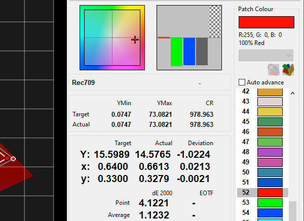
(Such simple colour controls have little, if any, effect on gamut, having a greater effect on the volumetric colours with the pre-defined Gamut, with Colour altering volumetric Saturation, and Tint/Hue altering the relative colour alignment) - To assist in the calibration process using the Colour control, put up 75% Red, 75% Green, and 75% Blue patches in turn, while performing Continuous Measurements, and adjust the TV's Colour control to get the best overall result
- For Tint, as it usually alters the balance between Red and Green, and for Hue, as it alters all colours simultaneously, put up 75% Yellow, and adjust Tint/Hue for the most accurate result
After calibration has been set as above, run a number of Volumetric Profiles, such as Gamut Sweep and Memory Colours, or better still, a full Volumetric Characterisation Profile, and verify volumetric colour alignment. Green points are below 1 dE, Orange between 1-2.3 dE, and Red over 2.3 dE.

Displays with Advanced colour calibration capabilities offer a greater level of colour control. including Gamut (within the physical constraints of the display), and can be calibrated to a greater level of colour accuracy. This is usually defined as Colour Space, and provides a User option for advanced adjustment of each colour in turn - Red, Green, and Blue primary colours, and sometimes Cyan, Magenta, and Yellow secondary colours (although such secondary adjustments should not be required in a well-designed display!).
- If not already done, from within the Settings menu select the desired colour space target, usually Rec709
- As with the previous Colour control, select Red, Green, Blue, and if available Cyan, Magenta, and Yellow in turn, and adjust the associated display controls to correct the probe measurement reading to match the Target chromaticity (xy) values
(With Cyan, Magenta, Yellow, it should be a question of checking after Red, Green, and Blue have been set) - On some TVs better results may be attained using 75% saturation colour patches, rather than 100%
- As with other calibration controls, the various adjustments may interact, so it will be necessary to re-visit most entries for a second, or even third time, verifying the final results
Different displays have different controls for colour adjustment - RGB or HSL for example - but the use of them is the same regardless. The aim is to always make the Actual measured readings match the Target values, as accurately as possible, using the two CIE diagrams and Yxy or Yuv values, depending on the chart chosen, in conjunction with the RGB/HSL Bars Widget, and Zoom Widget.
And Remember...
With any license level of ColourSpace, the workflows are really very simple, but very powerful, and knowledgeable users will soon understand that there are few limits to how ColourSpace can be used.
And that includes graphs layouts. A Ctrl + Click on any graph icon button will pop-put numerous independent floating graphs.